
Elektrostatischer Korrektor
Diese Seite wurde noch nicht übersetzt.
1 Introduction
We have developed a purely electrostatic corrector for the spherical and chromatic aberration and have incorporated it in collaboration with JEOL Ltd. into a prototype Focused Ion Beam (FIB) column. The resolution of this column could significantly be improved by this aberration correction.
2 The chromatic correction principle
The generation of negative chromatic aberration within the correction pieces of electrostatic correctors is difficult to understand in a straight forward way. In principle a superposition of electrostatic quadrupole and round lens fields can produce such a negative aberration. Scherzer [Optik 2(1947) 114-132] has shown in 1947 that the optimum negative aberration is generated, if superimposed fields fulfil the condition
\phi_2=\frac{1}{2}\phi''-\frac{1}{16}\frac{\phi^{'2}}{\phi}
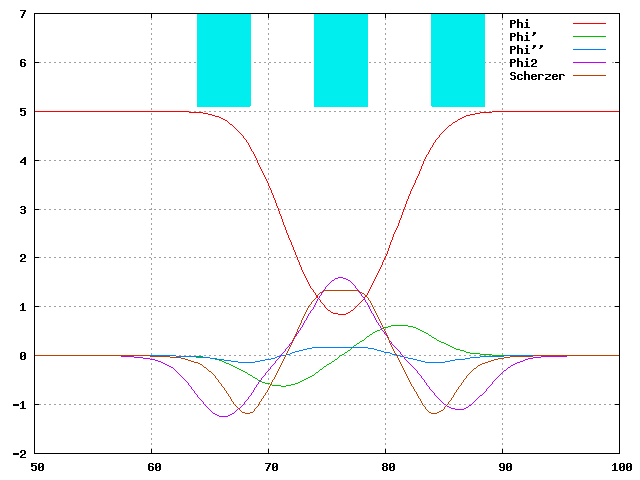
Figure 1 Approximation of Scherzer's condition in a correction piece consisting of 3 quadrupoles at different voltages
This work has been more recently reviewed by Rose and Weißbäcker, who invented the theoretical setup of CEOS's correctors.
Figure 1 shows the approximation of Scherzer's condition in a simulation for practical example of a correction piece. The condition is not perfectly fulfilled for the sake of ease of production, but the coincidence is good enough for chromatic correction.
3 Beam path and arrangement of the corrector within the column
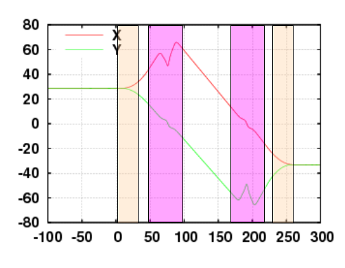
Figure 2 Beam path within a typical electrostatic corrector, also showing the location of quadrupoles (orange) and correction pieces (pink).
The corrective action described in the previous section is only valid in one section, for example the x-section, of the beam. For the y-section the chromatic aberration is then increased. This deleterious effect in the y-section has to be made ineffective by placing an astigmatic image in the centre of the correction piece, such that the y-ray crosses the axis in this area. The correction in y-direction has then to be carried out in a second correction piece, where the quadrupole field has the negative value of equation [1]. Of course an astigmatic image of the x-section has to placed in this correction piece.
A typical beam path of such a corrector is shown in figure 2.
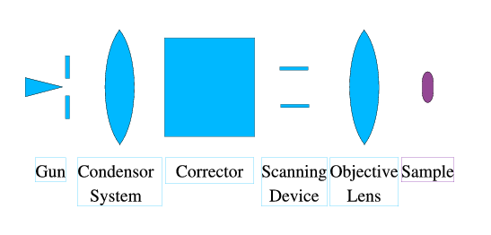
Figure 3 Typical arrangement of the corrector within the column of a scanning microscope
Since this type of corrector has comparatively large off-axial aberration, it only transfers very few image points. It can therefore only be used in scanning systems, where the scanning coils, which generate the off axial displacement, are positioned behind the corrector. This results in the typical arrangement of a corrected scanning system as depicted in figure 3.
4 Spherical correction
The correction of spherical aberration is carried out in the traditional way using octupoles, which are superimposed on to the correction pieces near the astigmatic images. If they are excited symmetrically, they only generate spherical aberration and some fourfold astigmatism. The latter can be compensated by means of octupoles placed somewhere at a (nearly) round beam path, for example as superposition on the outer quadrupoles of the corrector (see figure 2).
5 Fields of applications of electrostatic correctors
In principle electrostatic correctors can be used for electrons as well as for ions. The following table lists the pros and cons of electrostatic correctors compared to traditional electric/magnetic ones.
| electric/magnetic corrector | electrostatic corrector |
|---|---|
| Focusing and Cc-correction decoupled | Complicated coupling between these quantities |
| Magnetic hysteresis corrupts reproducibility | No hysteresis |
| Moderate higher order aberrations | Big higher order aberrations |
| Moderate sensitivity to alignment errors | High sensitivity to alignment errors due to very strong focusing power |
| Magnetic inhomogeneities create field distortions and parasitic aberrations | The field precision is only limited by machining tolerances. |
| The magnetic circuit dampens noise to the low kHz range | The corrector is sensitive to noise up to the GHz regime |
In conclusion of this table one can state:
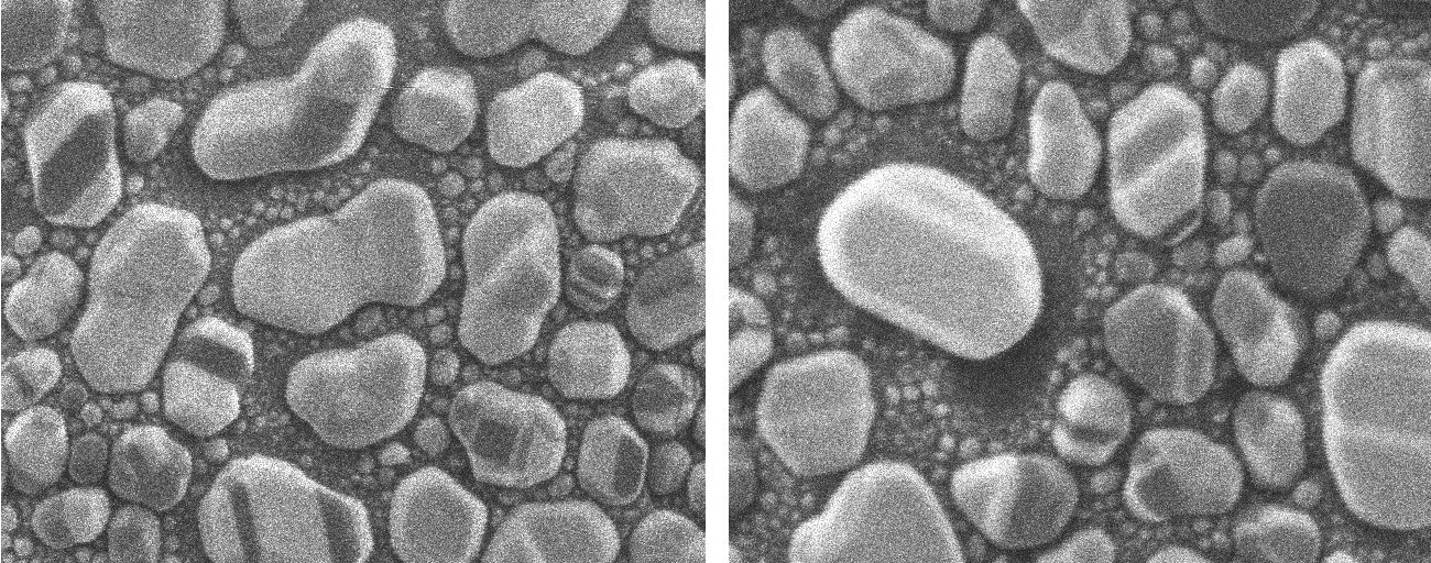
Figure 4: Comparison of resolution in FIB imaging mode (left uncorrected, right corrected) at low beam current (30 kV, 2 pA). Image width 2 µm.
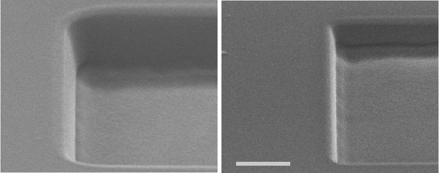
Figure 5: Comparison of milling edges in a FIB (left uncorrected, right corrected, milling parameters 30 kV, 1 nA). SEM-image: Scale bar 1 µm.
- For ion optics only electrostatic correctors can be used.
- Because of their better optical performance electric / magnetic correctors are preferred for electron optical applications.
- Where highest reproducibility is required and the higher order aberrations are not limiting the performance, electrostatic correctors can also be an alternative for electron columns.
6 Experimental results
We could demonstate that our prototype corrector corrects spherical and chromatic aberrations of a FIB system. As a result the resolution for imaging (low ion current, see figure 4) as well as for milling (high ion current, see figure 5) could significantly be improved.